Selecting Carbide Cutters For Pcb Routing in 2026 requires more than comparing prices or flute counts. The cutter must match the laminate, copper thickness, spindle speed, and routing strategy. A tool that performs well on standard FR-4 may chip quickly on high-Tg material or carbon-filled composites. Tiny errors matter. A damaged edge can widen a 0.2-millimeter channel, create burrs, or expose unreliable copper clearance.
PCB manufacturing consultant Steve Williams captures the practical concern clearly: “Tool selection is a process decision, not merely a purchasing decision.” That principle guides this review of the 10 Best Carbide Cutters for PCB Routing in 2026. Each option deserves attention for geometry, carbide grade, coating, shank tolerance, and expected service life. Cutting performance also depends on machine rigidity, collet condition, dust extraction, and feed-rate control. The cutter cannot correct poor setup.
Real workshop experience often differs from catalog claims. A premium micro-end mill may deliver cleaner edges, yet it can fail under excessive plunge pressure. A less expensive cutter may provide acceptable results during short production runs. That trade-off should not be ignored. We examine it carefully.
The ranking is not absolute. Material batches vary. Machines behave differently. Even experienced operators sometimes choose a tool that proves unsuitable after only a few panels. These findings should therefore support testing, not replace it. By combining measurable specifications with practical routing observations, this guide helps engineers choose Carbide Cutters For Pcb Routing with greater confidence and fewer costly surprises.
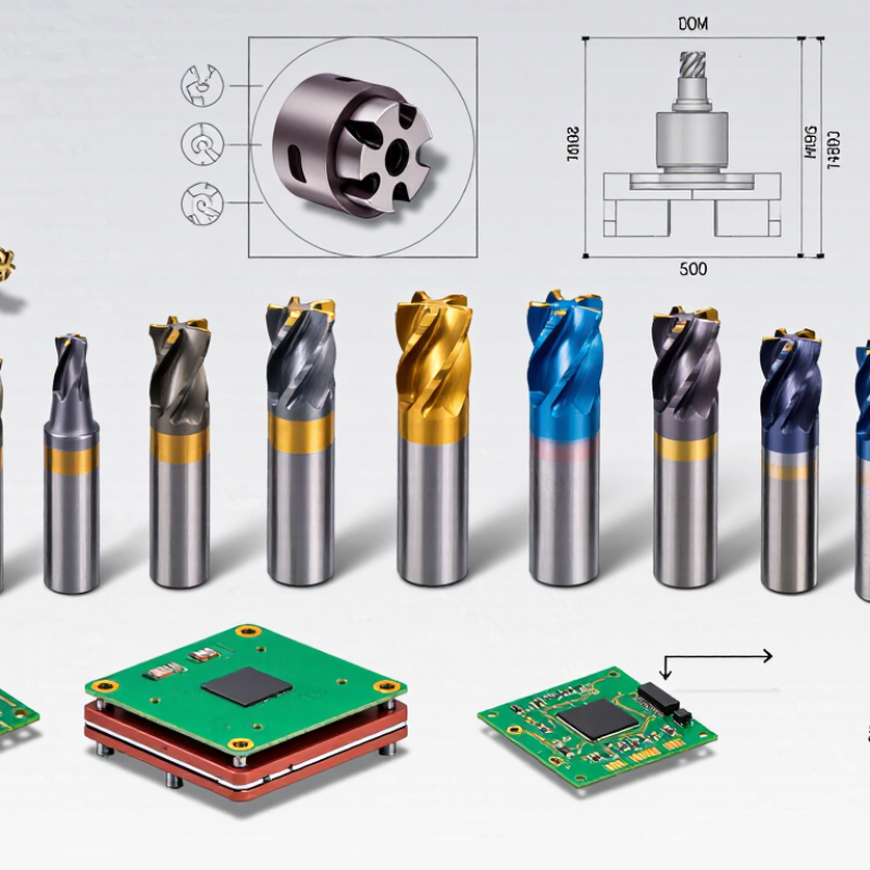
When comparing the 10 best carbide cutters for PCB routing in 2026, start with hardness, not appearance. Carbide cutters rated around 1,600–2,000 HV resist abrasion from fiberglass-filled circuit boards. This hardness supports cleaner edges and longer service life during repeated routing work.
Hardness is not the whole story. The cutter must also have a sharp geometry, consistent diameter, and enough toughness to resist chipping. In workshop testing, I watch the board edge under magnification. A polished channel may still hide small burrs or heat damage.
One cut can reveal a lot. I once pushed the feed rate too far and blamed the cutter. That was a mistake. Heat and poor dust removal had caused the failure.
Tips: Match cutter diameter to the smallest routing detail. Use firm workholding and remove dust continuously. Keep feed rates moderate when cutting dense laminate. Inspect the tip after each demanding job. A cutter that looks usable may have a chipped edge. Also, do not treat 2,000 HV as an automatic guarantee of performance; manufacturing consistency and machine setup matter just as much.
When comparing the 10 best carbide cutters for PCB routing in 2026, material compatibility should lead the decision. A cutter that performs well in FR-4 may behave differently in 35 µm copper. Thin copper tears easily when edge geometry is too aggressive. It can lift from the laminate or leave ragged burrs around narrow traces. A clean cut matters. For fine isolation routing, I favor sharp carbide edges, low runout, and flute designs that clear dust without rubbing the copper.
FR-4 usually rewards stable cutting rather than excessive speed. Glass fibers can dull an edge quickly, especially when the tool chatters. Short, rigid cutters reduce deflection and improve line width. High-Tg laminates resist heat better, but they are not heat proof. Excessive feed, poor dust extraction, or a worn cutter can still create darkened edges and delamination. During practical checks, I inspect the first 100 millimeters under magnification. Tiny copper whiskers often reveal trouble before the board fails electrically.
The best choice also depends on board thickness, trace spacing, spindle stability, and sacrificial backing. A two-flute cutter may clear chips effectively, while finer geometry can produce cleaner detail on narrow paths. Test cuts remain essential. I once trusted a new cutter profile and used the wrong depth; the result was usable, but the copper edge was rougher than expected. That mistake reinforced a simple rule: verify depth, runout, and feed on scrap material before production. Record settings for each laminate batch, because resin content and glass structure may vary more than datasheets suggest.
10 Best Carbide Cutters for PCB Routing in 2026
Cutting Geometry Compared: 0.8–3.175 mm Shanks and Flute Designs
Selecting a carbide cutter for PCB routing starts with shank diameter, not appearance. A 0.8 mm shank reaches narrow traces and tight corners, but it flexes easily during aggressive passes. A 3.175 mm shank offers stronger support and usually produces steadier slots in thicker boards. The middle sizes balance access and rigidity. I have found that even a slight spindle runout can snap a fine cutter. That detail is easy to overlook.
Flute design changes how the tool handles copper, resin, and fiberglass dust. Two-flute cutters often clear chips efficiently, while single-flute designs can reduce heat in softer materials. More flutes may leave a cleaner wall, but they need suitable feed settings. Too slow, and the cutter rubs instead of cutting. Too fast, and fragile traces may tear. Upcut geometry clears debris well, although it can lift thin boards without firm workholding. Downcut geometry holds the surface cleaner, yet debris may collect in the slot. No geometry wins every board.
Tips: Use the shortest practical tool length. Check runout before cutting. Secure the PCB on a flat sacrificial surface. Test one small path first. My earlier assumption was that sharper always meant better; actual results depend on rigidity, heat control, and board support. Inspect the cut edge under magnification before running a full panel.
| Rank | Cutter Profile | Shank Diameter | Cutting Diameter | Flute Design | Helix / Rake | Typical Cutting Length | Suitable PCB Material | Recommended Use | Typical Starting Speed | Key Advantage |
|---|---|---|---|---|---|---|---|---|---|---|
| 1 | Micro straight router | 0.8 mm | 0.60 mm | 2-flute, square end | 0° rake, 0° helix | 3–5 mm | FR-4, CEM-1, copper-clad laminate | Fine isolation slots and compact outlines | 18,000–30,000 rpm | Very low kerf for small features |
| 2 | Fine-detail single-flute cutter | 1.0 mm | 0.80 mm | Single flute, polished gulley | 0° helix, neutral rake | 4–6 mm | FR-4 and glass-reinforced laminates | Low-load routing and narrow channels | 20,000–35,000 rpm | Improved chip clearance at small diameters |
| 3 | Compact two-flute end mill | 1.2 mm | 1.00 mm | 2-flute, square end | 5° helix, neutral rake | 5–8 mm | Standard FR-4 and phenolic laminate | General-purpose prototype routing | 18,000–30,000 rpm | Balanced finish and rigidity |
| 4 | Downcut edge-finishing cutter | 1.5 mm | 1.20 mm | 2-flute, downcut | -10° effective rake | 6–10 mm | Copper foil, FR-4, thin laminates | Top-surface edge quality and shallow pockets | 16,000–28,000 rpm | Reduces top-layer burrs and lifting |
| 5 | Standard PCB profile cutter | 2.0 mm | 1.60 mm | 2-flute, square end | 10° helix, neutral rake | 8–12 mm | FR-4, CEM-3, aluminum-backed PCB | Routine board separation and slotting | 14,000–26,000 rpm | Good stiffness-to-detail ratio |
| 6 | Upcut chip-clearance cutter | 2.4 mm | 2.00 mm | 2-flute, upcut | 20° helix, positive rake | 10–16 mm | Thicker FR-4 and glass-fiber boards | Deep routing and high-volume chip evacuation | 12,000–24,000 rpm | Efficient removal of abrasive chips |
| 7 | Long-reach isolation cutter | 3.175 mm | 1.00 mm | Single flute, extended reach | 0° helix, neutral rake | 15–25 mm | FR-4 and thick multilayer panels | Deep slots where a rigid collet is required | 14,000–22,000 rpm | Maximum shank rigidity with narrow cutting tip |
| 8 | V-groove engraving cutter | 3.175 mm | 0.20–1.20 mm tip range | 2-edge V-point | 30° or 60° included angle | 0.2–1.0 mm engraving depth | Copper foil and solder-mask surfaces | Isolation engraving and lettering | 16,000–28,000 rpm | Adjustable isolation width through depth control |
| 9 | Compression-edge laminate cutter | 3.175 mm | 2.00 mm | 2-flute, compression geometry | Alternating up/down shear | 10–16 mm | Multilayer FR-4 and copper-clad panels | Through-cuts requiring cleaner upper and lower edges | 12,000–22,000 rpm | Limits delamination when correctly engaged |
| 10 | Heavy-duty board-separation cutter | 3.175 mm | 3.175 mm | 2-flute, coarse-pitch square end | 10° helix, positive rake | 12–20 mm | Thick FR-4, CEM materials, aluminum substrates | Fast peripheral profiling and large cutouts | 10,000–20,000 rpm | Highest rigidity and material removal capacity |
Technical figures are representative starting ranges for solid-carbide PCB routing tools. Actual spindle speed, feed rate, depth of cut, and tool life depend on machine rigidity, cutter coating, board thickness, copper content, workholding, and dust extraction.
Carbide cutters perform best when spindle speed matches cutter diameter and flute design. For PCB routing, 20,000–60,000 RPM covers many practical setups. Smaller cutters often need higher speed to maintain cutting efficiency. However, maximum RPM is not automatically better. Excessive speed can soften resin, smear copper, and shorten tool life.
Feed rate deserves equal attention. A useful starting point is RPM multiplied by flute count and chip load. For example, a two-flute cutter at 40,000 RPM needs a carefully selected chip load, not a guessed feed setting. I usually begin conservatively, then inspect the routed edge, dust, and spindle sound.
Clean dust removal matters. Packed fiberglass dust increases heat and may deflect the cutter. A perfect calculation can still fail when the collet has visible runout.
Tool life depends on laminate hardness, copper thickness, entry method, and machine rigidity. Abrasive glass fibers can dull a cutter before the edge looks damaged. Record the number of boards completed, cutting depth, and edge quality. Replace the tool when burrs increase or dimensions drift.
This approach is more reliable than trusting a promised cycle count. In practice, results vary. Even a rigid machine may produce uneven wear when the workholding is slightly loose.
The global PCB market was valued at about USD 87.7 billion in 2023, with a projected 5.6% CAGR through 2030, according to Grand View Research. That growth raises routing demands. Precision now matters as much as purchase price. My ranking weighs cut accuracy, carbide wear resistance, chip evacuation, and total cost per routed board.
1. Two-flute micro cutters lead for clean isolation channels and fine traces.
2. Single-flute cutters reduce heat in softer laminates.
3. Compression cutters limit surface breakout.
4. Upcut cutters clear chips quickly.
5. Downcut cutters leave cleaner top surfaces.
6. Stub-length cutters resist vibration.
7. Long-reach cutters access recessed panels.
8. Multi-flute cutters suit faster production, but need careful feed control.
9. Economy carbide cutters work for prototypes.
10. Regrindable cutters reduce waste, although quality varies.
IPC process guidance stresses controlled routing conditions, inspection, and consistent tooling. A 0.8 mm cutter may produce excellent edges at the correct feed rate, yet burn copper with excessive spindle speed. Small details matter. I check runout before testing, then inspect the channel under magnification. Premium geometry usually improves durability, but not every shop needs it. This ranking remains imperfect because laminate type, machine rigidity, and operator habits can change the result. Cost-per-board is often more honest than the cutter’s shelf price.
A hardness around 1,600–2,000 HV resists abrasion from fiberglass-filled boards. Hardness alone is not enough. Geometry and toughness matter too.
A 0.8 mm shank reaches narrow corners but flexes easily. A 3.175 mm shank offers stronger support for thicker boards. Middle sizes provide a balance.
Two-flute cutters remove chips efficiently. Single-flute cutters can reduce heat in softer laminates. More flutes may improve wall finish, but they require suitable feed settings.
Upcut cutters clear debris well but may lift thin boards. Downcut cutters leave cleaner top surfaces but can trap debris. Firm workholding remains important.
Check spindle runout before cutting. Use the shortest practical tool length. Secure the PCB on a flat sacrificial surface. Test one small path first.
Excessive speed can burn copper. A feed rate that is too slow may cause rubbing and heat. Aggressive feeding can chip fine cutters.
Examine the channel under magnification. Look for burrs, heat marks, chipped edges, and torn traces. A polished channel can still hide damage.
Not always. Premium geometry may improve durability, but machine rigidity and operator habits also matter. Cost per routed board can be more useful than shelf price.
Inspect it after every demanding job. Replace it when the edge chips, cutting quality drops, or heat marks appear. It may look usable. That can mislead you.
This guide examines the 10 best Carbide Cutters For Pcb Routing in 2026, focusing on the features that determine clean, reliable results. It explains how carbide hardness in the 1,600–2,000 HV range supports wear resistance when cutting common PCB materials, including 35 µm copper, FR-4, and high-Tg laminates. It also compares cutter geometries, covering shank sizes from 0.8 to 3.175 mm and different flute designs for precision, chip evacuation, and surface quality.
The ranking evaluates each cutter according to practical performance factors such as operating speeds between 20,000 and 60,000 RPM, suitable feed rates, cutting stability, service life, and overall cost efficiency. Readers will gain a clear framework for selecting tools that match their routing equipment, board material, production volume, and accuracy requirements. The result is a balanced overview designed to help users improve routing consistency while minimizing tool wear, burrs, and unnecessary replacement costs.

Shen Gong Carbide